All RC hobbyists have used a Brushless DC motor (BL-DC motor) for either a glider, stunt plane or tricopter along with an electronic speed controller (ESC). While it may not be feasible to use a breadboard ESC on a RC model, making a standalone ESC powered by an Arduino would make an interesting project.
Materials required for this project are:
1. Arduino Uno (or another model) ~ 20$
2. BLDC motor (I bought an A2212 13t from amazon.com) ~15$
3. 2200 mAh lipo battery (I used a Venom 20c 3s 2200mah ll.1 volt lipo battery. It is an overkill for this project but I already had it for another project) ~15$
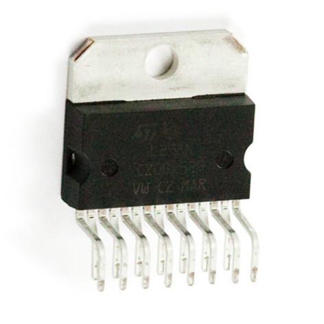
4. L298n H-bridge in Multiwatt package (You need 3 of these as BLDC motors are substantially more complex than their brushed counterparts)~7$
5. 830 point breadboard (and jumper wires) ~7$
Total Cost: <70$
Part 1: Theory
Sensored vs Sensorless Commutation
Sensored commutation is preferred as it provides information to the microcontroller about the position of the rotor or shaft. The microcontroller can then energize the optimal coil. In a sensorless system, the microcontroller guesses which coil to energize resulting in less than optimal performance.
There are two main sensored configurations. One way is to use Hall Effect sensors that are positioned in the motor. These sensors use magnetism to determine the position of the shaft. Not all motors have Hall Effect sensors and those who do are more expensive than sensor less ones. Another method uses back emf to determine the speed of the motor. This requires additional hardware and is far less precise than Hall Effect sensors.
Unipolar vs Bipolar
In a unipolar motor, one terminal is energized at a time and only half of the target coil is energized. In a bipolar motor two terminals is energized at a time and the entire target coil in energized. As a direct result,bipolar motors produce more torque. Bipolar motors are not perfect as back emf cannot be measured without a free terminal.
Reading the following site will help you understand the reasoning behind the circuits I created:
http://bldc.wikidot.com/p-esc-motor
Part 2: Circuit, Wiring and Explanation
I would have liked to use fritzing in order to demonstrate the circuit and code, however, the L298n H-bridge comes in a Multiwatt package with 15 staggered pins.
Basic experimentation will show that multiwatt packages are not suitable for breadboards and the pins will not fit nicely across the ravine (the gap in the middle of a breadboard). To get around this, carefully bend the longer pins till they fit decently on a breadboard.
video coming soon
Step 1: Power Rail
First step in wiring this circuit is to connect the power rails on the breadboard to the Arduino. In this project, we have to connect the Multiwatt to two different supplies: Supply Voltage (12+ volts) and Logic Supply Voltage (5 volts). It is important that this step is done care for a mix-up between these voltages can result in a fried Arduino.
I have created an image using fritzing to demonstrate the circuit. Note that VIN is the 12 volt supply voltage bypassing the voltage regulator.
Step 2: L298n Pinout
Here is a nice diagram I found:
 Note that the short pins in the diagram are the ones that are bent.
In an l298n there are 2 independent 2 amp channels. Controlling a A2212 motor only requires 3 channels so the first time I attempted this project I used 2 l298n chips using 3 of the 4 total channels. That didn’t work out. The A2212 13t BLDC motor draws more than 6 amps and the l298n’s were getting dangerously hot. This time, I integrated 3 L298n’s , connecting each chips two channels in parallel for 4 amp output per chip (12 amps total).
Here is a diagram I created to show where to connect each L298n’s pins to the Arduino.
L298n 1:
|
Pin |
Name |
Connection |
|
1 |
Current Sensing A |
Gnd |
|
2 |
Output 1 |
Connect a wire to it, but leave the other end unattached |
|
3 |
Output 2 |
Connect a wire to it, but leave the other end unattached |
|
4 |
Supply Voltage Vs |
Connect this to the power rail connected to Vin |
|
5 |
Input 1 |
Arduino Pin 2 |
|
6 |
Enable A |
Arduino Pin 3 |
|
7 |
Input 2 |
Arduino Pin 4 |
|
8 |
Gnd |
Gnd |
|
9 |
Logic Supply Voltage Vss |
Connect this to the power rail connected to Arduino 5V |
|
10 |
Input 3 |
Connect to Input 1 |
|
11 |
Enable B |
Connect to Enable A |
|
12 |
Input 4 |
Connect to Input 2 |
|
13 |
Output 3 |
Connect to Output 1 |
|
14 |
Output 4 |
Connect to Output 2 |
|
15 |
Current Sensing B |
Gnd |
Before moving on, run this code on the Arduino (Power the Arduino via USB):
Take a multimeter and hook the red probe to the free wire coming from Output 1 and the black one to Output 2. If everything is correct the multimeter should read +5 volts. You can now unplug the loose wire from Output 2.
Repeat the same steps for L298N 2 and 3. Make sure you connect:
L298n 2 Input 1 to Pin 7
L298n 2 Input 2 to Pin 8
L298n 2 Enable to Pin 9
L298n 3 Input 1 to Pin 12
L298n 3 Input 2 to Pin 13
L298n 3 Enable to Pin 11
and change the variable declarations at the top of the test code to match with the chip you are testing.
You have now finished the circuit. If you have followed the steps carefully, each L298n should have 1 wire coming out from them. Connect each wire to a motor terminal using alligator clips (Order does not matter. Just make sure all terminals are connected).
Part 3: Logic and Code
That circuit I created above, took time to come up with. There were two main problems I had to deal with:
1. How was I going to deal with the absence of a ground (all there terminals have to be live at one point)
2. What was I going to do with the unneeded output 2
The first problem was solved by thinking of ground as negative. Therefore to complete a circuit between terminals 1 and 2 I would set L298n 1 Output 1 to +12 volts and L298n 2 Output 1 to -12 volts or vice versa depending on what was needed.
The second problem was not really a problem, but my “solution” was one. Without thinking I hooked all three motor driver’s output 2 to ground. On my multimeter the voltages dropped and it was obvious that I created a short (Nothing broke as I was using a 5 volt supply). The correct way to deal with the unneeded outputs was leaving them floating and disconnected.
Some more necessary theory:
Six Phase Motor Control
In six phase motor control, each phase should energize a coil adjacent to the one energized in the previous step. If this is done correctly the rotor is dragged around in a circle creating a revolution. Repeat this with tempo and the motor is spinning!
The six phases:
1. C+A-
2. C+B-
3. A+B-
4. A+C-
5. B+C-
6. B+A-
Note each terminal is labeled A, B, C and + is setting a terminal to high and – sets it to low.
i.e. A+B- means setting terminal A to +12 volts and terminal B to -12 volts
Timing
Another important part of BLDC motor is timing. How much time should be spent on each phase? I couldn’t find a mathematical model relating voltage to timing so I experimented. Here is what I found:
1. You cannot jump from standstill to a 10 microsecond timing, you need to increase speed slowly.
2. You can however go from standstill to a 3 millisecond timing.
3. The smallest timing possible using a 12 volt battery is 135 microseconds
4. Timing is dependent on voltage. As the battery drains, the minimum timing increases and the speed decreases.
5. Decrementing the timing by 1 microsecond every loop works well
Code
The code for this circuit is fully functional. Aside from 6 phase commutation, I also implemented intermediate commutation mode and bipolar drive. The code is commented and will work without modifications on the above circuit. The code is not perfect and reverse spin is still a problem I will need to solve. I have attempted back emf measurement but have not finished yet.
https://www.dropbox.com/s/sug693f5y2l8wjf/FwdRev.ino?dl=0
Part 4: Additional Information
Bipolar
Recall 6 Phase commutation, there one terminal was free. For example, in step 1, terminal B was floating. Wouldn’t we get more holding torque if we energized all three terminals? We do this like this.
In visualizing the next part, it is important to realize that a motor spins the shaft in a circle. For this reason, step 1 is after step 6.
To come up with the six bipolar steps, take Phase 1 and Phase 6 (C+A- and B+A-). One can see that both steps have terminal A set as Low. Therefore the bipolar step between them is: C+B+A-. Do this again with Terminal 1 and terminal 2 (C+A-B-) and so on.
Intermediate
Intermediate spin is just a combination of 6 phase commutation and bipolar commutation. Intermediate commutation results in a smoother motion.
Videos and images or this project can be found in the following dropbox link:
Have a question? Please leave a comment.
 RSS Feed
